KOMUNIKASI SPI
1. Hardware [kembali]Push Button
LED
Buzzer
Power Supply
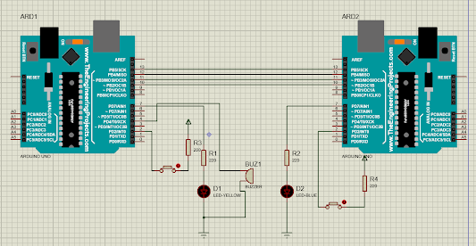
2. Rangkaian Simulasi [kembali]3. Listing Program [kembali]//MASTER
#include<SPI.h> //Library for SPI
#define LED 7
#define button 2
#define buzzer 4
int buttonvalue;
int x;
void setup ()
{
Serial.begin(115200); //Starts Serial Communication at Baud Rate 115200
pinMode(button,INPUT); //Sets pin 2 as input
pinMode(LED,OUTPUT); //Sets pin 7 as Output
pinMode(buzzer, OUTPUT); // Sets pin 7 as Output
SPI.begin(); //Begins the SPI commnuication
SPI.setClockDivider(SPI_CLOCK_DIV8); //Sets clock for SPI communication at 8 (16/8=2Mhz)
digitalWrite(SS,HIGH); // Setting SlaveSelect as HIGH (So master doesnt connnect with slave)
}
void loop()
{
byte Mastersend,Mastereceive;
buttonvalue = digitalRead(button); //Reads the status of the pin 2
if(buttonvalue == HIGH) //Logic for Setting x value (To be sent to slave) depending upon input from pin 2
{
x = 1;
}
else
{
x = 0;
}
digitalWrite(SS, LOW); //Starts communication with Slave connected to master
Mastersend = x;
Mastereceive=SPI.transfer(Mastersend); //Send the mastersend value to slave also receives value from slave
if(Mastereceive == 1) //Logic for setting the LED output depending upon value received from slave
{
digitalWrite(LED,HIGH);
Serial.println("Master LED ON");
digitalWrite(buzzer, HIGH);
Serial.println("Master buzzer ON");
delay(5000);
}
else
{
digitalWrite(LED,LOW); //Sets pin 7 LOW
Serial.println("Master LED OFF");
digitalWrite(buzzer, LOW);
Serial.println("Master buzzeR OFF");
}
delay(50);
}
//SLAVE
#include<SPI.h>
#define LEDpin 7
#define buttonpin 2
volatile boolean received;
volatile byte Slavereceived,Slavesend;
int buttonvalue;
int x;
void setup()
{
Serial.begin(9600);
pinMode(buttonpin,INPUT); // Setting pin 2 as INPUT
pinMode(LEDpin,OUTPUT); // Setting pin 7 as OUTPUT
pinMode(MISO,OUTPUT); //Sets MISO as OUTPUT (Have to Send data to Master IN
SPCR |= _BV(SPE); //Turn on SPI in Slave Mode
received = false;
SPI.attachInterrupt(); //Interuupt ON is set for SPI commnucation
}
ISR (SPI_STC_vect) //Inerrrput routine function
{
Slavereceived = SPDR; // Value received from master if store in variable slavereceived
received = true; //Sets received as True
}
void loop()
{ if(received) //Logic to SET LED ON OR OFF depending upon the value recerived from master
{
if (Slavereceived==1)
{
digitalWrite(LEDpin,HIGH);
Serial.println("Slave LED ON");
}else
{
digitalWrite(LEDpin,LOW); //Sets pin 7 as LOW LED OFF
Serial.println("Slave LED OFF");
}
buttonvalue = digitalRead(buttonpin); // Reads the status of the pin 2
if (buttonvalue == HIGH) //Logic to set the value of x to send to master
{
x=1;
}else
{
x=0;
}
Slavesend=x;
SPDR = Slavesend; //Sends the x value to master via SPDR
delay(500);
}
}
Visual Designer
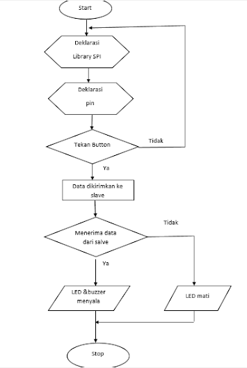
Flowchart Master
Flowchart Slave
Pada percobaan ini diberikan kondisi berupa menambahkan Buzzer sebagai input. Sehingga input yang tersedia adalah LED dan Buzzer.
5. Video [kembali]
6. Analisa [kembali]
1. Apakah termasuk komunikasi simplex, half duplex atau duplex?
Pada percobaan ini, proses pengiriman data terjadi secara bersamaan.Master mengirimkan perintah ke slave kemudian secara bersamaa salve menghidupkan led, slave akan mengirimkan perintah ke master sehingga led dan buzzer di master akan menyala. Hal ini berarti komunikasi yang digunakan adalah komunikasi duplex.
2. Apabila serial begin pada lave diubah jadi 9600,apa yang tejadi?
Serial begin digunakan untuk mengarue kecepatan transfer data. Apabila pada slave diganti maka proses transmisi data tidak berjalan lancar.
3. Apa fungsi clock speed pada percobaaan ini?
Clock speed digunakan untuk mengarut kecapan SPI. Clock speed 16Hz lebih cepat dari 8Hz. Semakin tinggi angkanya maka kecepatan clock akan semakin tinggi.
File Proteus - Download
File Program - Download
Video Rangkaian - Download
Datasheet Buzzer - Download
Datasheet LED - Download
Datasheet Arduino Uno - Download


Tidak ada komentar:
Posting Komentar